With the need for increased load capacity on existing lines, it is economically attractive to run a line at a higher temperature than originally designed. A higher operational temperature allows for a higher current. This approach avoids the need to buy new conductor or to strengthen or replace existing poles.
However, running a line at high temperatures, over about 100°C, may have problems, especially in an older line.
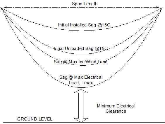
Sag in a conductor is determined by a combination of thermal elongation and a function of temperature and tension. All sag-tension calculations give typical results as shown in figure 1.

At high temperatures, assumptions found in common methods of heat balance and sag-tension calculations may lead to underestimates of sag especially for long span lengths, say over 300m. These span lengths occur more often in transmission lines but can be found in distribution and sub-transmission lines.
The errors that occur in calculations of high temperature lines can be due to:
- Temperature differences between strands
Sag calculations assume all strands in the conductor are the same temperature. Actually, the temperature difference between the centre of the conductor and its surface is a function of the current density, the number of layers, the tension and the conductor diameter. - Effect of temperature on conductor properties
It is assumed conductors properties such as final elastic modulus are constants, independent of temperature and stress. But they are not, for example for aluminium the elastic modulus decreases by about 5% /100°C. - Calculation of Mean Equivalent Span (Ruling Span)
The principle of a mean equivalent span is that the horizontal tension in all spans in a strain section is the same. However at high temperatures in a strain section with unequal length spans, tension varies more in short spans than in long spans. - Inexact “knee-point” temperature for non-homogeneous conductors
ACSR conductors (steel core with Aluminium outer strands) are commonly used for longer spans. Calculations assume there is a definite temperature at which the stress in the aluminium wires is zero. It is now known that there is typically a range of 10-20°C. - Higher steel content in older conductors
Older ACSR conductors have a relatively higher steel content than newer conductors. As conductors age under tension the aluminium strands elongate non-elastically. This behaviour also affects the knee-point temperature.
These factors are the most common and most significant causes of errors in calculations of sag, which in the worst case can lead to a sag error exceeding 2m for temperatures above 100°C in 300m spans. The table below shows sag results given by a range of different uncertainties.
|
Typical error magnitudes in high temperature sag calculations | |||
|
ACSR Drake |
ACSR Condor |
ACSR Tern | |
|
Aluminium area (strands) |
403 mm2 (26) |
403 mm2 (54) |
403 mm2 (45) |
|
Steel area (strands) |
66 mm2 (7) |
53 mm2 (7) |
28 mm2 (7) |
|
Final tension at 20oC |
25 800 N |
23 150 N |
19 100 N |
|
Equivalent span length |
250 m |
250 m |
250 m |
|
Sag at 20°C |
4.84 m |
5.06 m |
5.36 m |
|
Effect of calculation methods on final 120 ºC sag: | |||
|
Calculation assuming constant modulus |
7.76 m |
7.78 m |
8.53 m |
|
Graphical method with no Al compression |
7.00 m |
7.53 m |
8.53 m |
|
Graphical method with typical 20 MPa maximum compression |
7.32 m |
7.73 m |
8.53 m |
|
Additional sag errors at 120 ºC : | |||
|
Temperature difference core/surface |
+0.03 m |
+0.05 m |
+0.06 m |
|
Change of elastic modulus vs. temperature |
+0.15 m |
+0.11 m |
+0.06 m |
|
High temperature creep |
0 |
0 |
+0.50 m |
|
Multiple span effects |
+0.6 to -1.0 |
+0.5 to -0.9 m |
+0.5 to -0.8 m |
|
Effect of core magnetisation losses |
0 |
+ 0.07 m |
+0.05 m |
|
Effect of manufacturing temperature |
+/- 0.14 |
+/- 0.12 |
0 |
Conclusion
For distribution lines with long spans and high operational temperatures designers may want to allow for extra clearance to compensate for these uncertainties in the sag calculation.
Our power line design software Poles ‘n’ Wires makes it easy to calculate and check tensions and clearances.
References
Douglass,D, Motlis, Y, Seppa, T.O, IEEE’s Approach for increasing transmission line ratings in North America.
CIGRE 2004, Conductors for the Uprating of Overhead Lines