In literature you will find statements like this describing how to analyse a timber distribution pole:
Because directly embedded wood poles are generally very flexible, it has traditionally been assumed that all the transverse load is picked up by the guys, leaving no moment at the base of the pole. With this “column” analysis, the wood pole acts as pure compression member which is only checked against buckling. Design of Guyed Electrical Transmission Structures, ASCE no 91
Is there justification that this is a valid approach?
A pole can be modelled in one of two ways—being free to move at the base (like a hinge) or being fixed at the base.

Hinged Pole
Figure 1 is a free body diagram of a pole with one stay and a tipload (equivalent load applied at pole tip). The pole is modelled as hinged at ground level.
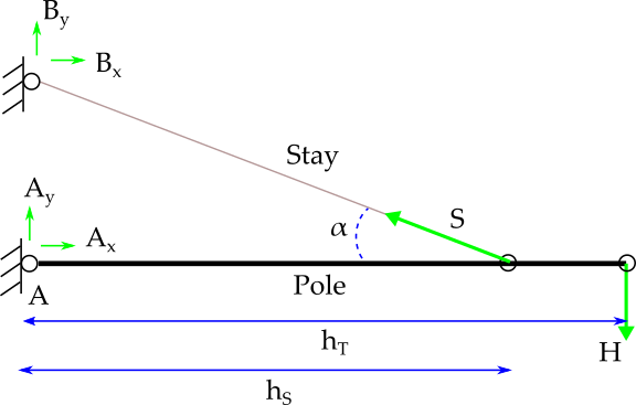
The system is in static equilibrium so the equations that apply are
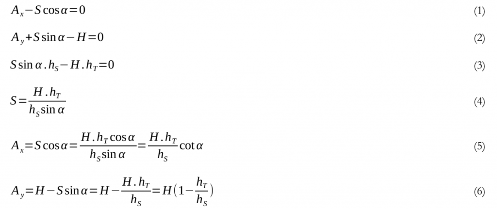
Equation 3, the bending moment at the pole base, equals zero by definition—the pole is free to rotate about the base. All horizontal resistance is provided by the stay and equation 4 shows that the tipload H is transferred in full on to the stay, increased by factors due to attachment heights and the angle of the stay.
The compressive load in the pole is Ax (eqn 5) and tension in the stay wire is given by equation 4.
These observations show the quotation from Design of Guyed Electrical Transmission Structures is valid if the pole is modelled as hinged.
Fixed Pole
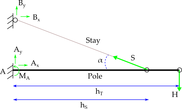
Similar to figure 1, figure 2 is the free body diagram for a pole modelled as fixed at the base. The load is distributed between pole and stay according to the ratios
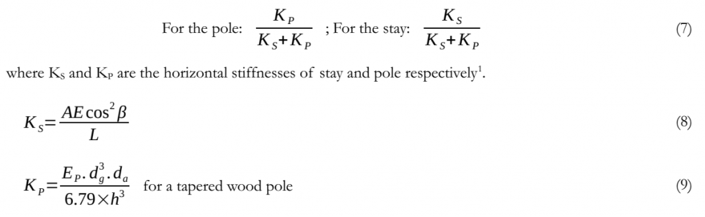
| A | cross-sectional area of stay |
| E | modulus of elasticity of stay |
| L | length of stay wire |
| β | angle between ground and stay = 90 – α |
| EP | modulus of elasticity of pole |
| dg | groundline diameter of pole |
| da | tip diameter of pole |
| h | pole height above ground |
Looking at some realistic values:
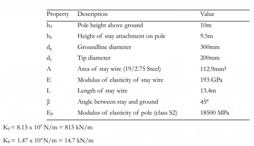
Equation 7 shows that the stay carries 813 / (813+14.7) = 98% of the transverse load. In reality, because of ground movement and creep, the stay could be considered as carrying all the load. KP is directly proportional to EP and KS is directly proportional to E so even for a combination of the least flexible timber and the weakest cable the stay will still carry the majority of the transverse load.
This exercise shows the quotation from Design of Guyed Electrical Transmission Structures is also valid if the pole is modelled as fixed at the base.
Conclusion
Both models show the stay carries most of the load. One benefit of the “hinged pole” method is the material properties of the pole and stay are not required. For many distribution poles a design is performed using “generic” equipment for which the properties are not known at design time.
Another benefit of the hinged pole method is it does not rely on the foundation to provide bending moment resistance. For a distribution pole it is more desirable (easier to repair and safer for the public) for the foundation (usually natural earth or similar material) to give way than for the pole to snap. It is much easier to push a pole back to vertical and repack the foundation than to replace a broken pole.
The pole loading module in our software Poles ‘n’ Wires currently models a pole as hinged at the base.