How Can We Help?
Bending moment at Stay attachment
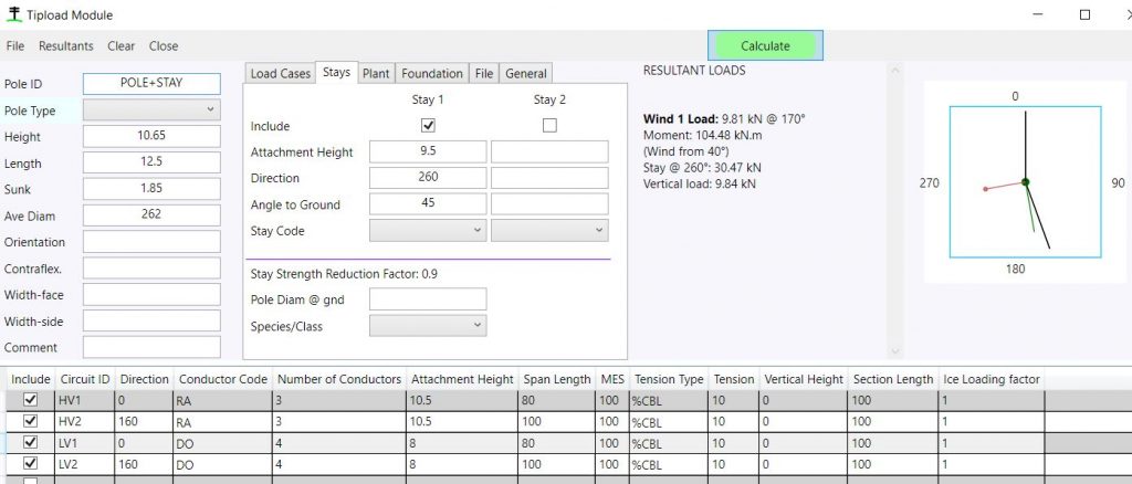
The bending moment at the stay attachment point (used to check the pole will not fail at that point) is the vector summation of the bending moments of all circuits on the pole above that point. This is a concern only for the highest stay if there is more than one. You can model this check in the tipload module in this way:
- Create the tipload as usual.

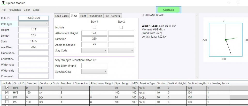
2. Untick Include for all circuits below the stay attachment height.
3. Change the attachment height for circuits above the stay to [cct attachment height – stay attachment height]—in this example that is 10.5 – 9.5 = 1.0
4. Change the pole height to [pole height – stay attachment height] ie 10.65 – 9.5 = 1.15
5. Untick Include for the stay/s.
6. Do the calculation.
This gives you the tipload acting at the stay attachment point due to circuits above the stay. If you know the pole properties (species or strength class) and dimensions you can use the Pole Strength module to determine the strength of the pole at the stay attachment height to compare against the tipload.

The wind on pole is calculated using the original average diameter however the effect of that inaccurate diameter in the adjusted tipload is negligible.