How Can We Help?
Ground line and Poles
The purpose of this article is to lay out the relationship between chainages and eastings/northings for the groundline, poles and circuits.
A ground line can be entered manually or through an import file eg spreadsheet.
In the profile view (the main window of the Profile module) what you are seeing is a perspective that is perpendicular to each ground line data element irrespective of what direction the ground line is running. It is as if the ground line/profile is straightened out.
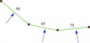
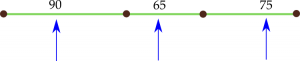
The blue arrows indicate your perspective looking at the profile window on the screen.
Chainage
Chainage is a horizontal distance along the line route, from the start of the profile (0) increasing to the right of the screen. Each ground line data point (if using chainage/level) is assigned chainage, as is each pole.
Easting/Northing
Ground line data points and poles are also assigned an easting/northing. The easting/northing of the groundline is displayed in the Groundline summary grid and is not editable. The pole information is visible on the Poles>Details tab under Properties.
When the ground line is entered manually Northing is always 0 and Easting equals the chainage.
If you have imported a groundline data file eastings/northings are read from the data file and stored with the ground data points and poles.
Profile window
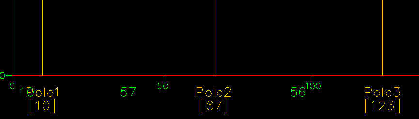
On the profile you will see a number under the pole ID. This is the chainage of the pole, eg for Pole2 it is 67. The number under the ground line between poles is the span length, eg 57 between Pole1 and Pole2, and is calculated from the easting/northing of the 2 poles, not from the chainges.
Circuit span length ie between 2 poles, is calculated from the easting/northing of the poles. The span length (always a horizontal distance) is displayed in the right margin when the mouse moves over a circuit line in the profile display. In this figure the span length is 155.
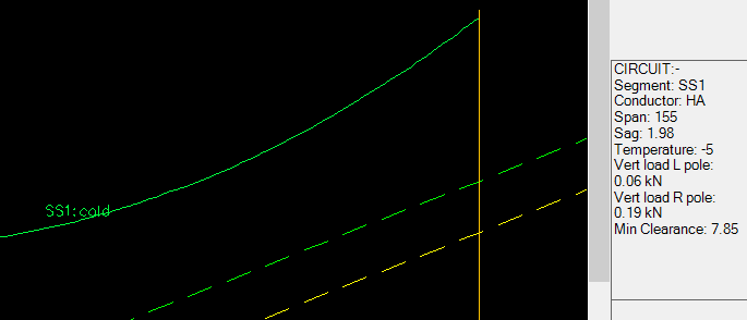
Sag is calculated from conductor properties, tension and span length. The conductor curve is drawn using pole chainages, conductor attachment height on each pole, ground line height at pole chainages and sag.
The ground line and poles in the profile view are drawn using chainages of the ground data points and poles.
The plan view is drawn using eastings/northings of ground points and poles.
Clearance between circuit and ground is measured using the ground line height at the selected chainage and the circuit curve height at the chainage.
Moving a pole
When you move a pole by editing its chainage the pole is moved along the ground line and given a new easting/northing determined by its new position on the groundline. Because the circuit span lengths are calculated from easting/northing the new Ruling span (Mean equivalent span) and sags are all correctly updated.
If you move a pole by manually editing its easting/northing the relationship between chainage and easting/northing is no longer easily determined. (This is why you should only edit the easting/northing if you are sure you know what you are doing.) The chainage assigned to the pole will probably not be correct. Span lengths and sags will still be correct but ground clearances visible in the profile window or displayed by the Measure function are not necessarily correct.