How Can We Help?
Model a head/pole stay
Design of Guyed Electrical Transmission Structures (ASCE no 91) says
Because directly embedded wood poles are generally very flexible, it has traditionally been assumed that all the transverse load is picked up by the guys, leaving no moment at the base of the pole. With this “column” analysis, the wood pole acts as pure compression member which is only checked against buckling.
That means the pole is treated as if it supports no part of the tipload and the load is transferred in full to the stay wire and thence to the bollard/ supporting pole.
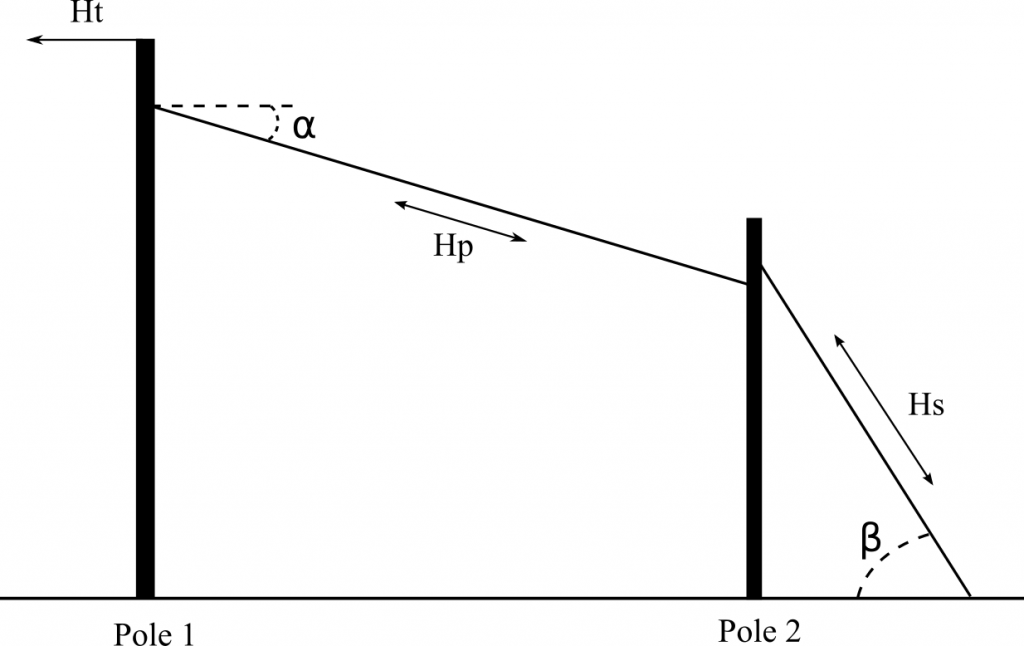
If there are no mains conductors on the bollard pole the scenario can be modelled in this way:
Tipload on main pole
- set up the tipload for the main pole (pole 1 in figure 1) as usual
- add the stay to the pole, specifying the details for the stay:
- attachment height
- direction – towards the support pole (pole 2)
- angle to ground – use the reclining angle of the stay wire – α in figure 1
- calculate the tipload for the load case you want to examine
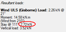
The tipload result shows the load on pole 1 with the stay in place. The load in the stay wire is also shown. This is the load that is transferred to the second pole.
Tipload on supporting pole
- Create the tipload for the supporting pole (pole 2). If the supporting pole has a back stay add this too.
- Using the Plant 1 tab add a fixed load (figure 2). The direction will be back towards the pole 1. The fixed load magnitude will be the load calculated for the stay wire in step 3.
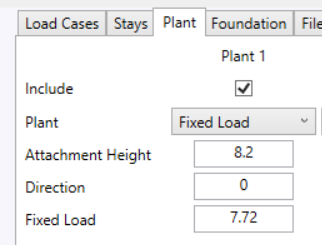
When the tipload for this second pole is calculated it will now include the load transferred from the main pole.
The load in the stay wire that is transferred to pole 2 could be reduced by cosine of the angle α, however for simplicity that could be ignored; the method given above will be conservative.