How Can We Help?
Reset pole chainages
This function alters the pole chainages based on each pole’s easting/northing, following an edit to the groundline. An example follows.
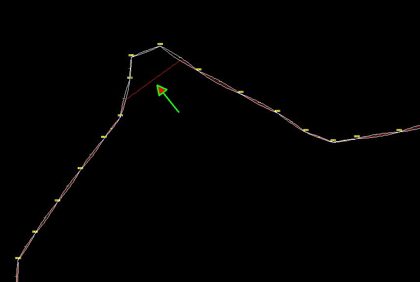
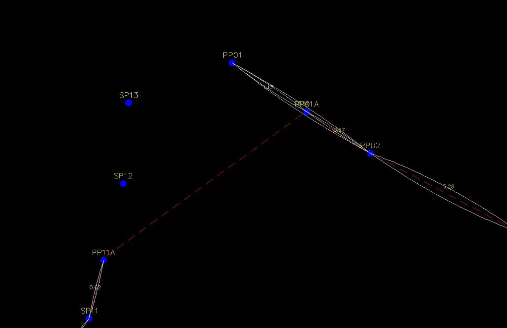
This is a part plan view of an existing profile. The green arrow points to a new groundline segment—the top corner is going to be removed from the line of poles. The detail below shows that poles SP12, SP13 and PP01 are being taken out and the line will run directly from PP11A to PP01A.
In this project this change to the groundline was accomplished by manually editing the profile file to remove the existing groundline and replacing it with a newly surveyed groundline that omits this section of the existing line route.
Usually chainages are assigned to poles on the basis of where the pole sits on the groundline, starting from the zero mark. The poles shown above can be deleted from the profile without difficulty, however the chainage of the poles to the right of this edited section of the groundline will no longer be correct, meaning that circuit clearances are probably not correct. (Span lengths are always correct because they are calculated from pole eastings/nothings.)
The Reset Pole Chainages function reassigns a chainage to each pole using the pole’s easting/northing to locate the corresponding distance along the groundline.
A message is shown if a pole is more than a certain distance from the nearest groundline segment and that pole’s chainage is not altered.