Conductor Blowout

Introduction

When wind acts on a conductor span the conductor blows to the side. This is an important consideration in checking clearances to objects like buildings or for creating an easement for the line. Blowout may also be relevant to ensuring conductors don't arc due to being too close together.

There are several variables that affect the blowout distance and a few different methods to perform the calculation. The simplified calculation referred to in this article will give the most conservative result (worst-case).

In the calculations commonly used for distributions lines the conductor is viewed as unrestrained—as if it were attached to frictionless hinges.

Blowout distance (the horizontal distance between the position of the conductor under no wind conditions and its position under wind load) is derived from the swing angle. The general equation for swing angle (\(\varphi_c \) from vertical) is

\(\large  \varphi_c=\tan^{-1} \left( \frac{P d}{w} \right ) \)

where (in suitable units)

P = wind pressure
d = conductor diameter
w = distributed conductor weight

The blowout distance may be greater or smaller than the vertical sag, depending on the conductor diameter and weight and stringing tension. In an examination of about 3000 calculations using about 600 different conductors, blowout was greater than sag in less than 60% of the scenarios.

Variables

Blowout calculations are only approximations of the behaviour of the line (this is true of most calculations for power lines). Wind action varies with time and location and could be described as random within a statistical range. Only the component of wind perpendicular to the line causes blowout yet weather information is not usually that detailed.

Conductors have mass and therefore inertia so wind gusts (peak wind speeds over a short time period) may not cause a reaction in the wire. Various studies of blowout (swing) angles show that measured angles are smaller than theoretically expected as shown in this graph.


Methodologies

There are different ways the blowout can be calculated—

Do you use no wind sag or wind-loaded sag? Some literature says to incorporate the effect of wind loading on conductor tension1 2, which in turn affects the effective conductor weight. Some documents start with the no wind sag3. Other documents are not specific.

What conductor temperature to use? Do you use a high temperature, on the basis that at high temperatures the conductor elongates therefore will have a bigger blowout distance? Or do you use a temperature at or near everyday conditions, because a significant wind will blow the heat out of the conductor reducing its temperature to approximately ambient4?

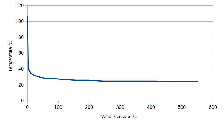
A conductor's temperature is dependent on the ambient temperature, current flowing in the wire and wind. When wind blows on the conductor the heat is mostly blown away and the temperature drops significantly, rapidly approaching ambient. This chart was generated from values calculated in the Conductor Ratings module of Poles 'n' Wires for a typical span of Krypton conductor.

Poles 'n' Wires

When calculating blowout in Poles 'n' Wires, manually in the sag-tension module or as part of the report in the Profiler, you need to have previously selected in Options parameters for blowout temperature and wind pressure. The software currently uses the wind-loaded sag in calculations as the majority of references seem to use this method.

In Poles 'n' Wires blowout is calculated with no ice loading and ignores the effect of any insulators.

Insulators

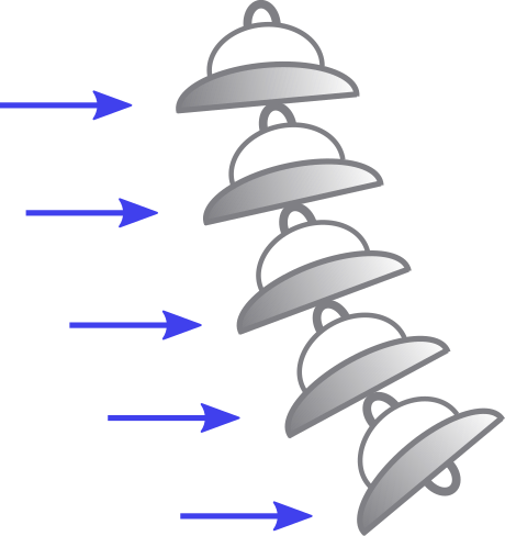
The deflection of suspension insulators can be calculated in the same way as the deflection of the conductors. However the calculation is tedious because each individual insulator in the string presents a different area to the wind as shown in this diagram.

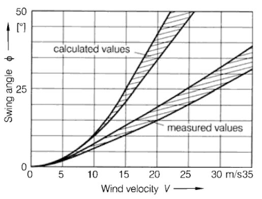
There is a simple and very cautious approximation. The swing angle of the insulators won't be greater than that of the conductor except in very short spans, therefore the swing angle of the supported conductor can be used as the swing angle of the insulator string. This may overstate the horizontal displacement of the insulator string but that is preferable to underestimating it.

Bibliography

Friedrich Kiessling, Peter Nefzger, Joao Felix Nolasco, Ulf Kaintzyk, "Overhead Power Lines: Planning, Design, Construction". Springer, 2014
IEC 60826, Design Criteria of overhead transmission lines. 2003
AS/NZS 7000:2016, Overhead line design. Standards Australia, 2016
BS EN 50341-1:2001, Overhead electrical lines. British Standards, 2001
Slegers, James Michael, "Design of resource to backbone transmission for a high wind penetration future" (2013). Graduate Theses and
Dissertations
. 13248.
A El Gayar, Z Abdul-Malek, I El-Shami, " Wind-Induced Clearances Infringement of OverheadPower Lines ". IJ Comp Elec Eng 2014
Allen Clapp, "Calculation of Horizontal Displacement of Conductors Under Wind Loading Toward Buildings and Other Supporting Structures". IEEE Transactions on Industry Applications, 1994

  1. AS/NZS7000 could be interpreted that way
  2. Since the wind-displaced sag in the conductor is affected by the both the wind and weight forces, a resultant force can be calculated and used as a substitute for conductor weight in the sag and tension calculations to obtain the sag along the swing angle under wind loading conditions. Calculation of Horizontal Displacement of Conductors, 1994, A Clapp
  3. The effective conductor dead weight results from the weight span without considering the increase in tension due to wind action. Overhead Power Lines, 2014, Keissling et al.
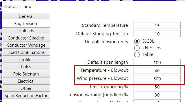
  4. a higher temperature need not be used as an assumed wind value of 40 mph (6 psf)) has quite a cooling effect. RUS 1724e200